


 |
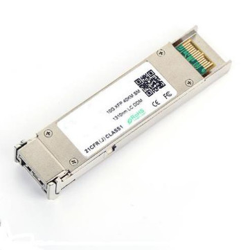
10Gbps 1310nm XFP Optical Transceiver for 40KM Transmission Distance in Slow or Fast Axis
Product Details:
| Place of Origin: | Guangdong, SHENZHEN |
| Brand Name: | TAKFLY |
| Certification: | CE,ROHS,REACH,ISO9001,ISO14001 |
| Model Number: | XFP-TK1392-LC40 |
Payment & Shipping Terms:
| Minimum Order Quantity: | 1 Pices |
|---|---|
| Price: | US$0.01 ~ US$1200/PC |
| Delivery Time: | 3-7working days |
| Payment Terms: | L/C, D/A, D/P, T/T, Western Union, MoneyGram |
|
Detail Information |
|||
| Ratio: | 50/50 | Center Wavelength: | 1450nm |
|---|---|---|---|
| Insertion Loss: | ≤0.3dB | Package Weight: | 10g |
| Package Type: | Bare Fiber, 900um Loose Tube, 2mm Cable | Wavelegth: | 1310nm |
| Axis Alignment: | Slow Axis Or Fast Axis | Wavelength Range: | 1310nm, 1550nm |
| Application: | Optical Communication Systems | Splitter Ratio: | 98/2 |
| Storage Temperature: | -40~+85℃ | Port Number: | 1x2 |
| Fiber Length: | 1m | Fiber: | PM Corning 980nm Fiber |
| Power Handling Capacity: | High Power | ||
| Highlight: | 40KM XFP Optical Transceiver,1310nm XFP Optical Transceiver,10Gbps XFP Optical Transceiver |
||
Product Description
-
TAKFLY XFP-TK1392-LC40 Small Form Factor 10G (XFP) transceivers are compliant with the current XFP Multi-Source Agreement (MSA) Specification1.They comply with 10-Gigabit Ethernet10GBASE-LR/LW per IEEE 802.3ae and 10G Fiber Channel. Digital diagnostics functions are available via a 2-wire serial interface, as specified in the XFP MSA. The transceiver is RoHS compliant and lead-free per Directive 2002/95/EC3.
Features
- Hot-pluggable XFP footprint
- Supports 9.95Gb/s to 11.3Gb/s bit rates
- XFI Loopback Mode
- RoHS-6 Compliant (lead-free)
- Power dissipation <1.5W
- Case temperature range: -5°C to 70°C
- Maximum link length of 20km
- Uncooled 1310nm DFB laser
- Full Duplex LC connector
- No Reference Clock required
- Built-in digital diagnostic functions
-
Standard bail release mechanism
Applications
- 10GBASE-LR/LW 10G Ethernet
- 10G Fiber Channel
- SONET OC-192 SR-1 SDH STM I-64.
Absolute Maximum Ratings
| Parameter | Symbol | Min | Typ | Max | Unit |
| Maximum Supply Voltage | Vcc3 | -0.5 | 4.0 | V | |
| Storage Temperature | TS | -40 | 85 | °C | |
| Case Operating Temperature | Tcase | -5 | 70 | °C |
Electrical Characteristics(TOP = -5 to 70 °C, VCC3 = 3.13 to 3.45 Volts)
| Parameter | Symbol | Min | Typ | Max | Unit | Ref. |
| Supply Voltage #2 | Vcc3 | 3.13 | 3.45 | V | ||
| Supply Current – Vcc3 supply | Icc3 | 450 | mA | |||
|
Module total power |
P |
1.5 | W | 1 | ||
| Transmitter | ||||||
| Input differential impedance | Rin | 100 | Ω | 2 | ||
|
Differential data input swing |
Vin,pp | 120 | 820 | mV | ||
| Transmit Disable Voltage | VD | 2.0 | Vcc | V | 3 | |
| Transmit Enable Voltage | VEN |
GND |
GND + 0.8 |
V | ||
| Transmit Disable Assert Time | 10 | us | ||||
| Receiver | ||||||
|
Differential data output swing |
Vout,pp | 340 | 650 | 850 | mV | 4 |
| Data output rise time | tr | 38 | ps | 5 | ||
| Data output fall time | tf | 38 | ps | 5 | ||
| LOS Fault | VLOS fault | Vcc–0.5 | VccHOST | V | 6 | |
| LOS Normal | VLOS norm |
GND |
GND+0.5 |
V | 6 | |
| Power Supply Rejection | PSR | 7 |
Notes:
- Maximum total power value is specified across the full temperature and voltage range.
- After internal AC coupling.
- Or open circuit.
- Into 100 ohms differential termination.
- These are unfiltered 20-80% values
- Loss of Signal is open collector to be pulled up with a 4.7k – 10kohm resistor to 3.15 – 3.6V. Logic 0 indicates normal operation; logic 1 indicates no signal detected.
- Per Section 2.7.1. in the XFP MSA Specification1.
Optical Characteristics (TOP = -5 to 70 °C, VCC3 = 3.13 to 3.45 Volts)
| Parameter | Symbol | Min. | Typ | Max. | Unit | Ref. | |
|
Average Optical Power |
P |
0 |
3 |
dBm |
|||
|
Optical Wavelength |
λ |
1290 | 1310 | 1330 |
nm |
||
|
Sidemode Suppression ratio |
SSRmin |
30 |
dB |
||||
|
Optical Extinction Ratio |
ER |
4 |
dB |
||||
|
Transmitter and Dispersion Penalty |
TDP |
2 |
dB |
||||
|
Average Launch power of transmitter |
P |
-30 |
dBm |
||||
|
Tx Jitter |
Tx |
Per 802.3ae requirements |
|||||
|
Relative Intensity Noise |
RIN |
-130 |
dB/Hz |
||||
| Parameter | Symbol | Min. | Typ | Max. | Unit | Note |
|
Receiver Sensitivity |
RSENS |
-16 | dBm | 1 | ||
|
Input Saturation Power (Overload) |
Psat |
-6 | dBm | |||
|
Wavelength Range |
λC |
1270 | 1610 | nm | ||
|
Receiver Reflectance |
Rrx |
-27 | dB | |||
|
LOS De-Assert |
LOS |
-18 | dBm | |||
| LOS Assert |
LOS |
-25 | dBm | |||
|
LOS Hysteresis |
0.5 | 4 | dB |
Notes:
Measured with worst ER; BER<10-12@ 10.3Gbps, 231 – 1 PRBS.
Pin Assignment
![]()
![]()
![]()
General Specifications
![]()
Digital Diagnostic Functions
As defined by the XFP MSA1, The XFP transceivers provide digital diagnostic functions via a 2-wire serial interface, which allows real-time access to the following operating parameters:
- Transceiver temperature
- Laser bias current
- Transmitted optical power
- Received optical power
- Transceiver supply voltage
It also provides a sophisticated system of alarm and warning flags, which may be used to alert end-users when particular operating parameters are outside of a factory-set normal range.
The operating and diagnostics information is monitored and reported by a Digital Diagnostics Transceiver Controller (DDTC) inside the transceiver, which is accessed through the 2-wire serial interface. When the serial protocol is activated, the serial clock signal (SCL pin) is generated by the host. The positive edge clocks data into the XFP transceiver into those segments of its memory map that are not write-protected. The negative edge clocks data from the XFP transceiver. The serial data signal (SDA pin) is bi-directional for serial data transfer. The host uses SDA in conjunction with SCL to mark the start and end of serial protocol activation. The memories are organized as a series of 8-bit data words that can be addressed individually or sequentially. The 2-wire serial interface provides sequential or random access to the 8 bit parameters, addressed from 000h to the maximum address of the memory.
Mechanical Specifications
TAKFLY XFP transceivers are compliant with the dimensions defined by the XFP Multi-Sourcing Agreement (MSA).
![]()
XFP Transceiver (dimensions are in mm)
PCB Layout and Bezel Recommendations
![]()
XFP Host Board Mechanical Layout (dimensions are in mm)
![]()
XFP Detail Host Board Mechanical Layout (dimensions are in mm)
![]()
Regulatory Compliance