


 |
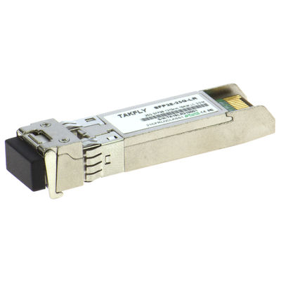
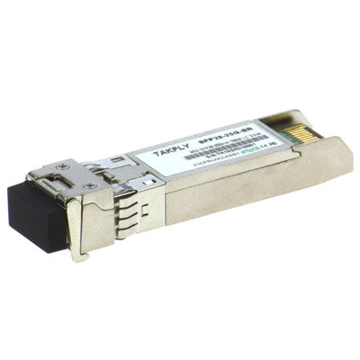
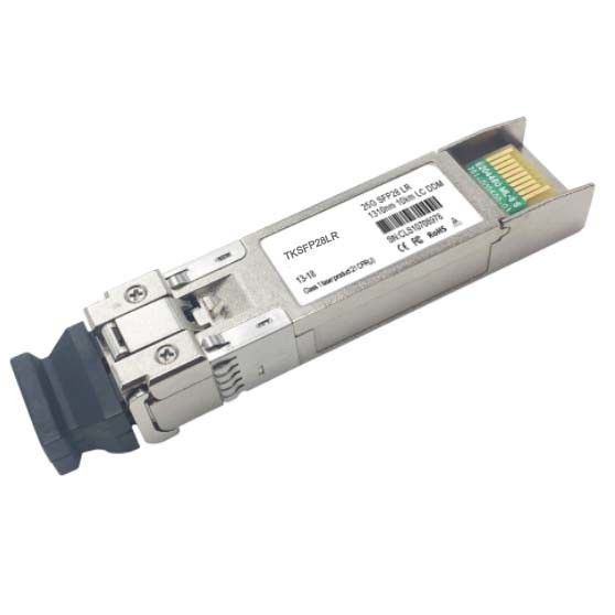
25G SFP28 CWDM 20km Transceiver SFP Module 1270nm 1370nm For CISCO HP Huawei
Product Details:
| Place of Origin: | China |
| Brand Name: | Takfly |
| Certification: | CE,ROHS,FCC,REACH,ISO9001,ISO14001 |
| Model Number: | TKSFP25GCW20 |
Payment & Shipping Terms:
| Minimum Order Quantity: | 1 piece |
|---|---|
| Price: | USD 60 ~ USD 100 |
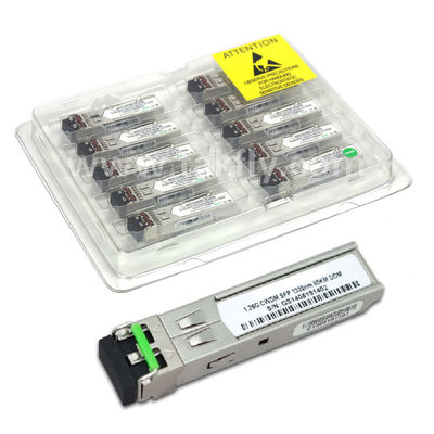
| Packaging Details: | blister box + spone + carton |
| Delivery Time: | 3-5 working days |
| Payment Terms: | T/T, Western Union, MoneyGram, Paypal, L/C |
| Supply Ability: | 30000pcs/month |
|
Detail Information |
|||
| Speed: | 25G Base | Transmission Distance: | 20KM |
|---|---|---|---|
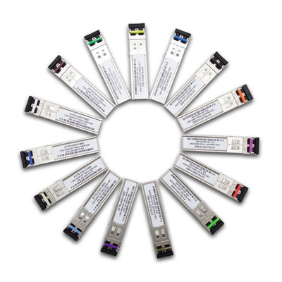
| Wavelength: | 1270~1370nm | Compatible Switch Brand: | CISCO/HP/Huawei/H3C/Juniper/ZTE/........ |
| Grade: | Commercial Grade/Industrial Grade | Fiber Type: | Singemode |
| Highlight: | 25G Transceiver SFP Module,SFP28 Transceiver SFP Module,25G SFP28 CWDM |
||
Product Description
25G SFP28 CWDM 20km Optica Transceiver SFP Module 1270~1370nm compatible with CISCO HP Huawei H3C Juniper ZTE
Optical Transceive Module Description
25G SFP28 transceiver module is designed to transmit and receive optical data over single mode optical fiber for link length 10km/20km. The SFP28 LR module electrical interface is compliant to SFI electrical specifications. The transmitter input and receiver output impedance is 100 Ohms differential. Data lines are internally AC coupled. The module provides differential termination and reduce differential to common mode conversion for quality signal termination and low EMI. SFI typically operates over 200 mm of improved FR4 material or up to about 150mmof standard FR4 with one connector.
Optical Transceive Module Product Features
- Supports 25GBASE(25Gb/s);
- Lane bit rate 25.78 Gb/s;
- Up to 20km transmission on SMF;
- DFB laser and PIN receiver for 6 CWDM waves(1270nm-1370nm);
- High speed I/O electrical interface (25GAUI);
- I2C interface with integrated Digital Diagnostic monitoring;
- SFP28 MSA package with duplex LC connector;
- Single +3.3V power supply;Maximum power consumption 1.2 W;
- Operating case temperature: Refer to Order info.
- Compliant to IEEE 802.3cc Draft3.0, SFF-8402 and SFF-8432;
Optical Transceive Module Applications
- 25GBase-CWDM
1. Absolute Maximum Ratings
| Parameter | Symbol | Min. | Typical | Max. |
| Storage Temperature | TS | -40 | - | +85 |
| Supply Voltage | VCC | -0.5 | - | +4.0 |
| Operating Relative Humidity | RH | - | - | +85 |
2. Recommended Operating Conditions
| Parameter | Symbol | Min. | Typical | Max. | Unit |
| Operating Case Temperature TKSFP25GCW20 | TC | -5 | - | +70 | °C |
| Operating Case Temperature TKSFP25GCW20I | TC | -40 | - | +85 | °C |
| Power Supply Voltage | VCC | 3.13 | 3.3 | 3.47 | V |
| Power Supply Current | ICC | - | - | 0.35 | A |
| Maximum Power Dissipation | PD | - | - | 1.2 | W |
| Lane Bit Rate | BRLANE | 24.3 | 25.78 | 26.5 | Gb/s |
| Transmission Distance | TD | - | 20 | km |
3. Optical Characteristics
| Transmitter | ||||||
| Parameter | Symbol | Min. | Typical | Max. | Unit | Notes |
| Center Wavelength | λ0 | 1XX0-6 | 1XX0 | 1XX0+6 | nm | |
| Average Launch Power | PTX_LANE | -3 | - | 2 | dBm | 1,2 |
| Spectral Width (-20dB) | σ | - | - | 1 | dBm | 3 |
| Optical Modulation Amplitude | OMA | -4 | - | 2.2 | dBm | 4 |
| Launch power in OMA minus TDP (min) | OMA_TDP | -5 | - | - | dBm | |
| Difference in launch power between lanes | PTX_DELTA_LANE | - | - | 3.6 | dB | |
| Average Output Power (Laser Turn off) | Pout-OFF | - | - | -30 | dBm | |
| Side Mode Suppression Ratio | SMSR | 30 | - | - | dB | |
| Extinction Ratio, 100GE | ER | 3.5 | - | - | dB | |
| Transmitter and dispersion penalty (TDP) | TDP | - | - | 2.7 | dB | |
| Optical Return Loss Tolerance | ORLT | - | - | 20 | dB | |
| Optical Eye Mask | Compliant with IEEE 802.3cc Draft 3.0 | |||||
| Receiver | ||||||
| Center Wavelength | λ0 | 1260 | 1380 | nm | ||
| Receiver sensitivity (OMA) | - | - | -12.3 | dBm | 5 | |
| Stress sensitivity (OMA) | - | - | -9.8 | dBm | 6 | |
| Receiver Overload | PIN-OL | 3 | - | - | dBm | |
| Reflectance | Ref | - | - | -12 | dB | |
| LOS Assert per lane | LOSA | -30 | - | - | dBm | |
| LOS De-assert | LOSD | - | - | -17 | dBm | |
| LOS Hysteresis | LOSH | 0.5 | - | 4 | dB | |
Notes:
1. Class 1 Laser Safety per FDA/CDRH and EN (IEC) 60825 regulations.
2. High Bandwidth Mode. Class 1 Laser Safety per FDA/CDRH and EN (IEC) 60825 regulations.
3. 20dB spectral width.
4. Equivalent extinction ratio specification for Fibre Channel. Allows smaller ER at higher average power.
5. At 5E-5 BER, KR4 FEC
6. Per IEEE802.3cc
4. Electrical Characteristics
| Transmitter (Module Input) | |||||||
| Parameter | Symbol | Min. | Typical | Max. | Unit | Notes | |
| Differential Data Input Amplitude | VIN,P-P | 90 | - | 800 | mVpp | ||
| Differential Termination Mismatch | - | - | 5 | % | |||
|
Tx_Disable |
Normal Operation | VIL | -0.3 | - | 0.8 | V | |
| Laser Disable | VIH | 2.0 | - | VCC+0.3 | V | ||
| Receiver (Module Output) | |||||||
| Differential Data Output Amplitude | VOUT,P-P | 185 | - | 425 | mVpp | ||
| Differential Termination Mismatch(1MHZ) | - | - | 5 | % | |||
| Output Rise/Fall Time, 20%~80% | TR | 12 | - | - | ps | ||
|
Rx_LOS |
Normal Operation | VOL | - | - | 0.2 | V | |
| Lose Signal | VOH | VCC-0.2 | - | - | V |
|
|
5. Pin Descriptions
![]()
| Pin | Symbol | Description | Ref. |
| 1 | VEET | Transmitter Ground (Common with Receiver Ground) | 7.1 |
| 2 | TFAULT | Transmitter Fault. Not supported. | |
| 3 | TDIS | Transmitter Disable. Laser output disabled on high or open. | 7.2 |
| 4 | MOD_DEF(2) | Module Definition 2. Data line for Serial ID. | 7.3 |
| 5 | MOD_DEF(1) | Module Definition 1. Clock line for Serial ID. | 7.3 |
| 6 | MOD_DEF(0) | Module Definition 0. Grounded within the module. | 7.3 |
| 7 | RS0 | Rate Select0, optionally controls SFP+ module receiver. When high input signaling rate>4.25 GBd and when low input signaling rate<4.25GBd | |
| 8 | LOS | Loss of Signal indication. Logic 0 indicates normal operation. | 7.4 |
| 9 | RS1 | Rate Select1, optionally controls SFP+ module receiver. When high input signaling rate>4.25 GBd and when low input signaling rate<4.25GBd | |
| 10 | VEER | Receiver Ground (Common with Transmitter Ground) | 7.1 |
| 11 | VEER | Receiver Ground (Common with Transmitter Ground) | 7.1 |
| 12 | RD- | Receiver Inverted DATA out. AC Coupled. | |
| 13 | RD+ | Receiver Non-inverted DATA out. AC Coupled. | |
| 14 | VEER | Receiver Ground (Common with Transmitter Ground) | 7.1 |
| 15 | VCCR | Receiver Power Supply | |
| 16 | VCCT | Transmitter Power Supply | |
| 17 | VEET | Transmitter Ground (Common with Receiver Ground) | 7.1 |
| 18 | TD+ | Transmitter Non-Inverted DATA in. AC Coupled. | |
| 19 | TD- | Transmitter Inverted DATA in. AC Coupled. | |
| 20 | VEET | Transmitter Ground (Common with Receiver Ground) | 7.1 |
Notes:
7.1 Circuit ground is internally isolated from chassis ground.
7.2 Laser output disabled on TDIS >2.0V or open, enabled on TDIS <0.8V.
7.3 Should be pulled up with 4.7k - 10kohms on host board to a voltage between 2.0V and 3.6V. MOD_DEF(0) pulls line low to indicate module is plugged in.
7.4 LOS is open collector output. Should be pulled up with 4.7k -10kohms on host board to a voltage between 2.0V and 3.6V. Logic 0 indicates normal operation; logic 1 indicates loss of signal.
6. EEPROM & DDM THRESHOLD
6.1 EEPROM
2 wire address 1010000X (A0h)
|
0~95 Serial ID Defined by SFP MSA (96 bytes) |
|
96~127 Vendor Speific (32 bytes) |
|
128~255 Reserved (128 bytes) |
6.2 DDM THRESHOLD
| Low Alarm | Low Warn | High Warn | High Alarm | |
| Temperature TKSFP25GCW20 | -10℃ | -5℃ | 75℃ | 80℃ |
| Temperature TKSFP25GCW20I | -45℃ | -40℃ | 80℃ | 85℃ |
| Voltage | 3V | 3.1V | 3.5V | 4V |
| Tx Bias | 10mA | 20mA | 80mA | 100mA |
| Tx Power | -4dBm | -3dBm | 2.5dBm | 3dBm |
| Rx Power | -14.4dBm | -12.4dBm | 2dBm | 2.5dBm |
Ordering Information
|
Part No. |
Data Rate |
Laser |
Fiber Type |
Distance |
Optical Interface |
Temp |
DDMI |
| TKSFP25GGLR | 25.78Gbps | CWDM DFB | SMF | 20KM | LC | -5~70 °C | Y |
| TKSFP25GGLRI | 25.78Gbps | CWDM DFB | SMF | 20KM | LC | -40~85 °C | Y |
CWDM WAVE=1270nm, 1290nm, 1310nm, 1330nm, 1350nm, 1370nm.
![]()
![]()